

Beamforming must also be adequately considered in immission determination. (Picture: Pixabay)
With 5G, some major technical innovations are making their way into the mobile communications industry, such as beamforming. It helps to use valuable frequency resources of the mobile communications cell more efficiently. But this approach is also of interest from the point of view of immission control. For this reason, scientists at the Institute of Radio Frequency Technology in Aachen, Germany, have taken a close look at the special alignment of the transmitting radiation.
Authors: Thomas Kopacz, Sascha Schießl, Anna-Malin Schiffarth, Dirk Heberling, IHF – Institute for High Frequency Technology, Aachen, Germany
The first part of the paper showed the background and the functionality of beamforming. In the following it is shown how the procedure for the execution of immission measurements looks like and which new complexity arises:
The 26th BImSchV defines limit values for both electric and magnetic field strength. It must be ensured that both field strength limits are complied with. In practice, it is usually sufficient to determine only one field strength value, since electric and magnetic field strength can be converted into each other from a certain distance from the transmitting antenna – in the so-called far field.
The distance at which the far field begins depends, among other things, on the operating frequency of the transmitting antenna and its dimensions. In publicly accessible areas around base stations, the distance is usually so high that it is sufficient to detect one field strength component. For the high-frequency electromagnetic fields used in mobile communications, the electric field strength is determined because it is easier to measure in this frequency range.
Portable spectrum analyzers
Immission measurements to determine the electric field strength are usually performed using portable spectrum analyzers. Spectrum analyzers measure the immission in a specific portion of the signal spectrum. The SRM-3006 meter from Narda Safety Test Solutions is widely used in the field of immission measurement technology.
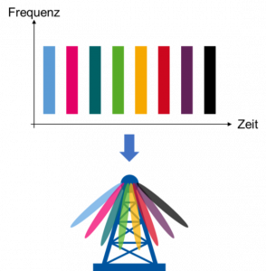
For 5G, this can be used to measure the immission within the frequency bandwidth of the SSB. These so-called frequency-selective measurements are used to determine the prevailing immission in a specific frequency range at the time of measurement. For the extrapolation to determine the maximum possible immission, the immission of the SSB is determined for 5G and the extrapolation is performed based on this.
In principle, the position of the SSB in the frequency spectrum can be determined using frequency-selective measurements and its immission measured. However, the SSB occupies the frequency spectrum only at certain times, and a large part of the time it may be occupied by traffic. Therefore, a conventional frequency-selective measurement may determine the immission of the traffic instead of that of the SSB.
Measurement independent of time
For this reason, there is the possibility in the field of measurement technology to carry out so-called code-selective measurements. This allows the signaling components relevant for the immission extrapolation to be decoded and only their immission components to be determined. In the case of 5G, part of the SSB is decoded (secondary synchronization signal, SSS). The great advantage of code-selective measurement is that it is independent of the traffic load in the cell at the time of measurement and can also distinguish between the immission components of different mobile radio cells that can be received at the measurement point.
As a rule, the electromagnetic fields reach the place of immission not only via the direct path, but additionally via several different paths due to reflections from buildings, the ground as well as other reflecting surfaces. This multipath propagation leads to a superposition of the electromagnetic fields arriving from different directions at the place of immission, resulting in constructive and destructive superpositions of the fields within small distances. As a result, spatially high fluctuations of the immission occur.
Since the 26th BImSchV requires that measurements of the immission be carried out at the point of impact with the strongest immission and that the limit values be complied with on the basis of the maximum measured values, the spatial maximum must also be determined during the measurement. This can be done, for example, with the help of the point grid method, in which the immission is measured at several fixed measuring points in the room. Another method for determining the spatial maximum is the so-called slewing method, in which the measuring antenna is slowly slewed through the room and the maximum occurring is recorded with the aid of the measuring device. The panning method can be carried out in a much shorter time compared to the point grid method, but provides the same accuracy. Based on the maximum spatial immission of the signaling signal (of the SSB for 5G), a projection is then made to the highest operational system utilization, as already explained in the previous section of the text.
Increased complexity due to beamforming
In the predecessor mobile generations 2G, 3G and 4G, as well as in 5G in the 2 GHz band, the signaling signal used as the basis for extrapolation and the actual traffic that provides the maximum immission are emitted with the same antenna radiation pattern.
A maximum of eight SSB beams can be emitted sequentially in the frequency band between 3.4 GHz and 3.7 GHz.
However, in the case that Massive MIMO antennas are used, signaling and traffic are beamed differently. SSB beams are used for signaling (SSB) and traffic beams are used for traffic. In the frequency band between 3.4 GHz and 3.7 GHz, a maximum of eight SSB beams can be radiated sequentially. Each SSB beam covers a different area of the mobile radio cell. The different orientations result in an envelope of SSB beams as shown in blue in the following figure:
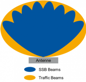
Envelope of the SSB and Traffic Beams
In contrast, the traffic beams can be aligned with a much finer angular resolution. This results in an envelope that is smoother and covers a larger angular range (orange).
The different radiation behavior of SSB and traffic beams has far-reaching consequences for the determination of the maximum immission when using massive MIMO antennas. In the extrapolation procedure, the gain difference between traffic and SSB beams must now also be taken into account because they can be bundled and aligned differently. Since this difference depends to a large extent on the angle at which the point of immission is located relative to the base station antenna due to the different beam alignment options, strictly speaking it must be determined individually for each measurement point.
State of research on immission determination
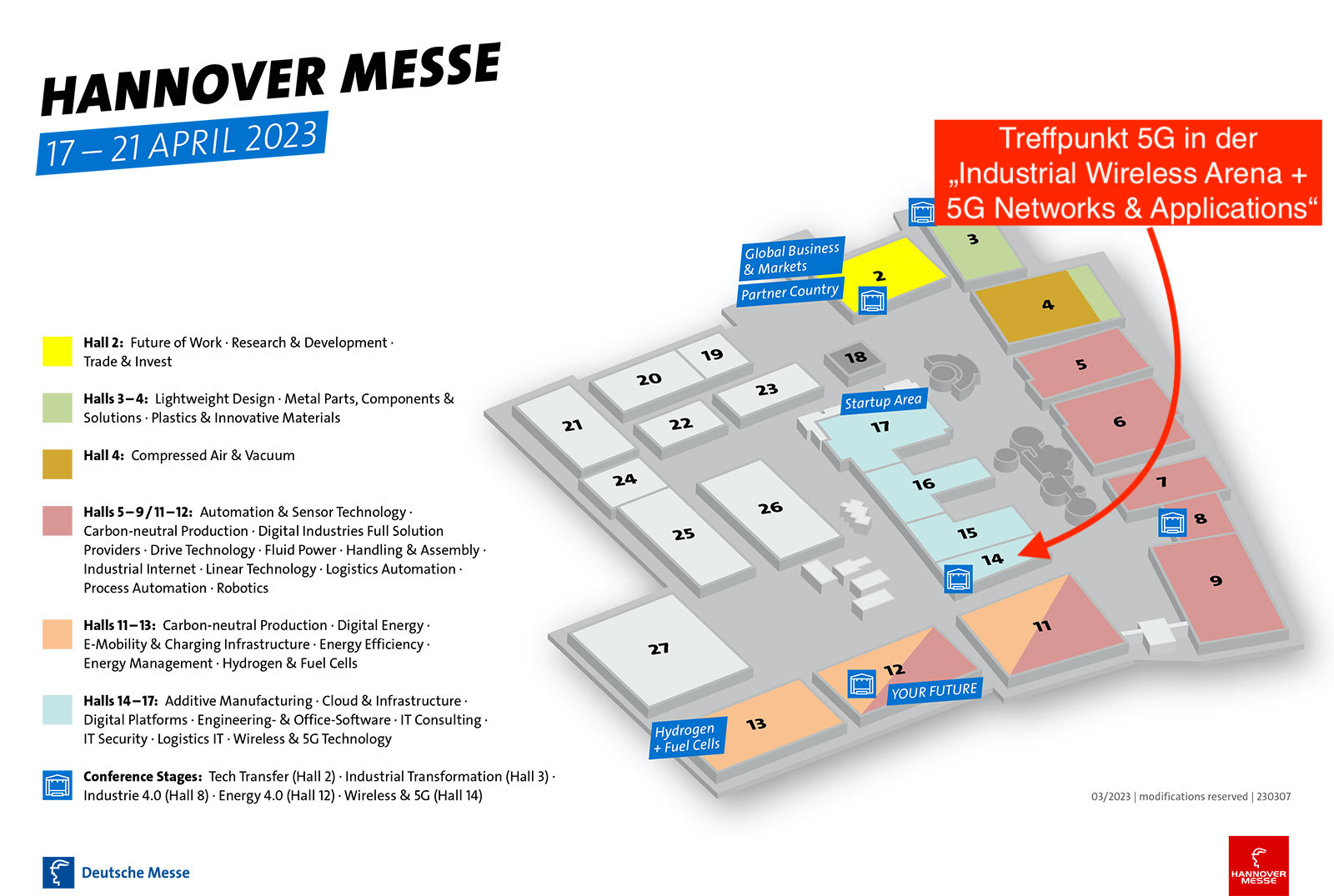
In addition to various international and national standardization committees that deal with the question of how beamforming can be adequately taken into account in the determination of immission, the Institute of High Frequency Technology (IHF) at RWTH Aachen University is also actively involved in contributing to answering this question. On behalf of the Federal Office for Radiation Protection (BfS), the IHF is currently conducting a research project in cooperation with the Technical University of Ilmenau and the EM Institute, in which possible extrapolation methods for determining the maximum immission are being metrologically tested. As part of this research project, typical and maximum immissions in 5G mobile radio cells with massive MIMO antennas are also being determined in order to quantify the effects of beamforming on immissions.
Read also the first part of the article here “Research on the immission of beamforming antennas“.
Contact the Author
Thomas Kopacz, M.Sc. Research associate
IHF – Institute for High Frequency Technology
RWTH Aachen University
Melatener Straße 25, 52074 Aachen
Tel: +49 241 80-27944
kopacz@ihf.rwth-aachen.de
www.ihf.rwth-aachen.de


Leave A Comment